Servo Valve Rebuild Process
Test Environment Standards
- Test stand hydraulic fluid maintained with a filtration of less than or equal to 3 micron nominal.
- Hydraulic Fluid temperate is maintained at temperature between 93 and 115 degrees Fahrenheit.
- Valve performance following refurbishment will meet or exceed OEM standards.
- Seal replacement using Viton® O-rings.
- Internal leakage held to 1.0 gpm or below.
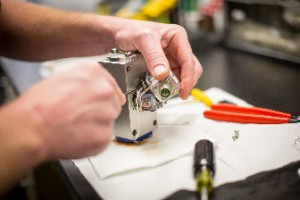
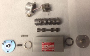 Ultrasonic Cleaning & Inspection of disassembled components for wear, corrosion, contamination, and damage.
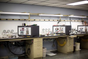
Dynamic Testing at 2000 PSI with fully automated servo valve test stands providing the most accurate and reliable test data in possible.
-
- Electrical Test in accordance with ANSI specifications measuring coil resistance, coil inductance, and insulation resistance
- Torque Motor Verification Testing measuring nozzle/flapper integrity and pressure, jet tube nozzle integrity, flow, and pressure, and torque motor magnetic field.
- Bias Verification testing null bias, flow bias, and spring bias.
Common causes of servo valve failure
Contamination, particulates, and degradation by-products in hydraulic fluid causes servo valve failure. Particle bombardment results in pitting of the bushing and spool assembly and nozzle and flapper assembly, causing excessive internal leakage and low spool end pressure.
Warranty
All new and reconditioned servo valves are backed up our own two-year warranty.
Nozzle| Flapper Type
Refurbishment for these valves should be on an 18-24 month cycle
Jet Pipe System Type
Refurbishment for these valves should be on a 24-36 month cycle
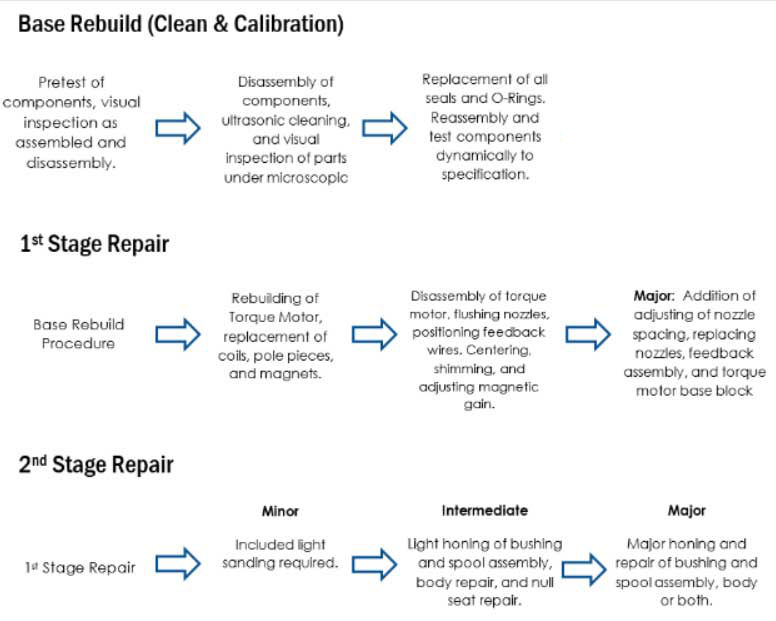
United Servo Repair Stage Overview
Servo Valve Component Overview
Nozzle/Flapper Servo Valve
There are two (2) main parts of a servo valve: a torque motor and a bushing/spool assembly. An electrical input signal to the torque motor coils creates a magnetic force which acts on the ends of the armature. This causes movement of the armature/flapper assembly within the flexure tube. Movement of the flapper restricts fluid flow through one nozzle which is carried through to one spool end, displacing the spool. The nozzle opening must be without flaw or contaminants, and the nozzle/flapper spacing must be precise for proper response.
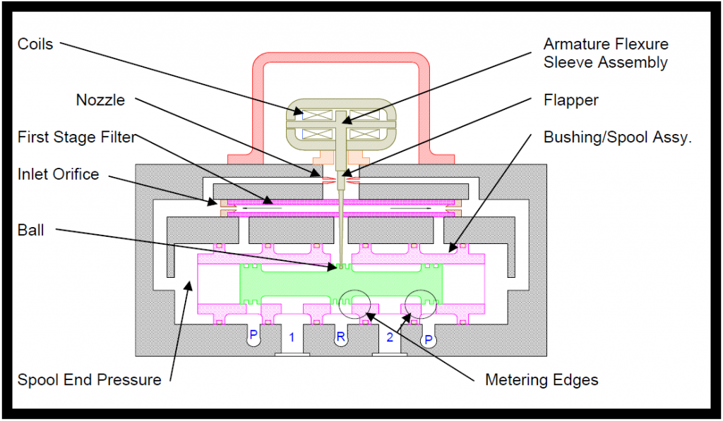 Slight movement of the spool opens the supply pressure port to one of the control ports and the return port to the other control port. The metering edges of the bushing/spool assembly are critical for accurate flow.
The spool motion also carries the ball end of the feedback spring, creating a restoring torque on the armature/flapper assembly. Once the restoring torque becomes equal to but, opposite the torque from the magnetic forces, the armature/flapper assembly moves back to the neutral position and the spool is held steady in a state of equilibrium (due to balanced spool end pressure) until the input signal changes to a new level.
In summary, the spool position is proportional to the input current and with constant pressure drop across the valve, flow to the load end is proportional to the spool position.
BUSHING/SPOOL EROSION
In certain circumstances, phosphate ester-based hydraulic fluid can degrade, resulting in decreased resistivity. This leads to excessive bushing/spool wear caused by electrochemical erosion. As the metering edges of the bushing /spool are eroded, the internal leakage through the servo valve increases at a rapid rate. The erosion causes uneven wear, resulting in loss of spool control and null bias shift.
THE NOZZLE/FLAPPER SYSTEM
The nozzle/flapper system must be free from defect or contamination for the spool end pressures to be stable and controllable. As the nozzle/flapper erodes or becomes blocked, the spool end pressures diminish. This results in uncontrollable spool movements, which includes the spool being forced to one side.
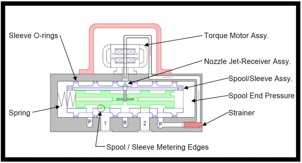
Jet Pipe Servo Valve
There are two main parts to a servo valve: a torque motor and a spool/sleeve assembly.
An electrical input signal to the torque motor coils creates a magnetic force, which acts on the ends of the armature. This causes a rotation of the armature/jet pipe assembly.
Movement of the armature/jet pipe assembly diverts more fluid through one receiver port relative to the other. The nozzle jet opening must be without flaw or contaminates, and the nozzle jet/receiver port spacing must be precise for proper response. The difference in flow between the two receivers is carried through to one spool end, causing displacement of the spool.
Slight movement of the spool opens the supply pressure port to one control port to the other control port. The metering edges of the spool/sleeve assembly are critical for accurate flow.
The spool motion also carries the ball end of the feedback spring, creating a restoring torque on the armature/jet pipe assembly. Once the restoring torque becomes equal to but opposite the torque from the magnetic forces, the armature/jet pipe assembly moves back to the neutral position and the spool is held steady in a state of equilibrium (due to balanced spool end pressure) until the input signal changes to a new level.
In summary, the spool position is proportional to the input current and, with constant pressure drop across the valve, flow to the load is proportional to the spool position.
SPOOL/SLEEVE EROSION
In certain circumstances, phosphate ester-based hydraulic fluid can degrade, resulting in decreased resistivity. This leads to excessive spool/sleeve wear caused by electrochemical erosion. As the metering edges of the spool/sleeve are eroded, the internal leakage through the servo valve increases at a rapid rate. The erosion causes uneven wear, resulting in loss of spool control and null bias shift.
THE NOZZLE JET/RECEIVER PORT SYSTEM
The nozzle jet/receiver port system must be free from defect or contamination for the spool end pressures to be stable and controllable. As the nozzle jet and receiver ports erode or become blocked, the spool end pressures diminish. This results in uncontrollable spool movements, which includes the spool being forced to one side.